FP2010 – FP, QE20 USER INTERFACE MODULE

FP2010 – FP, QE20 USER INTERFACE MODULE

Description

Installation Instructions

Fire Detection, Control Panels and System Accessories

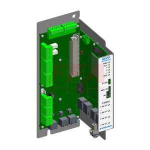
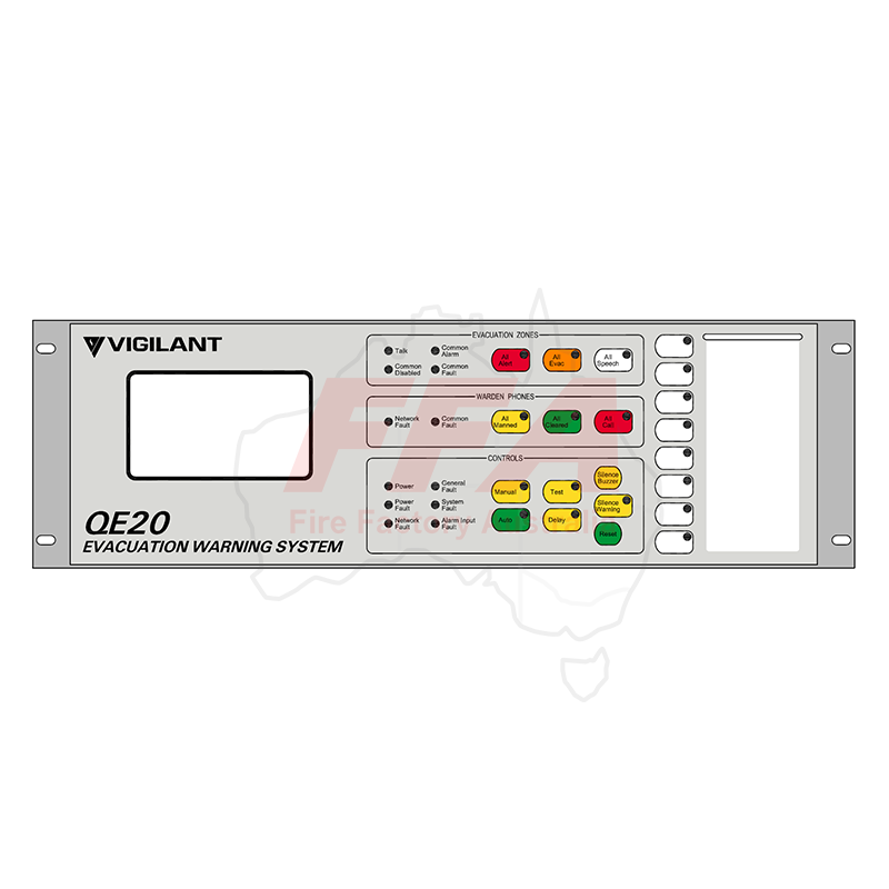
Main user interface module for QE20. It gives the master keyboard + LED indicators (system and all-zones), plus an LCD touchscreen for user functions and event/fault recall. It also supports 4 GP inputs + 4 GP open-collector outputsfor site logic.

Additional information

Models

SMX+650-1L-PS5, SMX+900-1L-PS5, SMX+900-1L-PS11, SMX+650-1L-PS11GL, SMX+12U1LPS11, SMX+28U1LPS11, SMX+40U1LPS11, SMX+40U1LPS11, LCM-320, LEM-320

Technical Specifications

Product Code FP2010
Product Name QE20 Master User Interface (MUI)
Main Function Master keyboard & LED display + LCD touchscreen for user functions and recall
Mounting Location QE20 inner door, 3U position (typically positions 3, 4, or 5 from top)
Mounting Hardware 4 × M4 × 10 screws
Earth Requirement Must be earthed to cabinet frame (earth tab to cabinet earth via supplied earth lead)
Power Supply 18–32V DC
Current Consumption 70mA typ @ 24V (all LEDs off)
80mA typ @ 24V (all LEDs & LCD on)
Ethernet 10/100Base-T RJ45 to Controller Ethernet Port 1
UBus (Extenders) Connect 8 Zone / 8 WIP Extender modules to MKI board (J2 or J3), daisy-chain supported
GP Inputs 4 × GP inputs, 4-band supervised (clean contact), 10k pull-up to +24V
GP Input States Short < 270Ω
Alarm 680Ω
Normal 10kΩ
Open > 20kΩ
GP Outputs 4 × open-collector outputs (no load supervision)
GP Output Rating 100mA max, < 1V on; 30V DC max off
Off-State Leakage Up to ~250µA (may cause LED glow; use bleed resistor if needed)
Extra Ports USB: not used (leave open) | Service Port: not used (leave open)
Kit Contents 1 × FP2010 Master User Interface
1 × RJ45 Ethernet lead (1.5m)
1 × 24V power loom with connectors
1 × LB0694 slide-in label (8 user buttons)
1 × LM0678 earth lead (450mm)
4 × M4 × 10 screws
1 × LT0706 installation instructions
Operating Conditions -5°C to +45°C, 10% to 93% RH (non-condensing)