| Product Code |
FP2005 |
| Description |
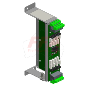
QE20 RS485 Network Module |
| Main Use |
Networking interface for QE20 (RS485 copper loop or fibre optic via fibre kit).
Also provides PA/WIP network audio links, GP I/O, and WIP audio chain routing. |
| When You Need 2 Modules |
If the site has a “Joined Audio Bus Segment” you need a 2nd module (Address = 2).
The 2nd module provides PA/WIP terminals for the joined segment. |
| Fibre Network Kit Options |
FP2024 – Fibre Network Kit (Single Mode)
FP2025 – Fibre Network Kit (Multi Mode) |
| Functions / Interfaces |
• 2 × isolated RS485 ports (Port A & Port B), 4-wire or link-selectable 2-wire
• Optional earth fault monitoring on RS485 (via EARTH MON links + Controller support)
• PA + WIP network audio bus connections (optional supervision via EOL links)
• 2 × GP inputs (fixed 4-state / 4-band supervision)
• 2 × GP outputs (open-collector, optional load supervision)
• 1 × RJ45 Ethernet to Controller
• 1 × TTL Serial port (for PIB in Fibre Kit)
• QEComms port (for VIF in Fibre Kit)
• WIP AUDIO CHAIN LEFT & RIGHT (to Controller and WIP/Input modules)
• RS232 ports (currently not supported – do not use)
• QBus port (currently not supported) |
| Power |
18–32 VDC |
| Current |
115 mA typical @ 24V |
| Operating Conditions |
-5°C to +45°C, 10–93% RH non-condensing |
| Address Setting |
Rotary switch: Address 1 = first (main) module, Address 2 = second module (if used).
(Use physical labeling on the switch; “0” position can differ between modules.) |
| RS485 Copper Links |
Port A (J12): 2-wire links usually fitted; remove for 4-wire (rare).
Port B (J13): same as above.
EARTH MON: enable on only one module per segment. Common approach: EARTH MON on Port A only. |
| PA / WIP Audio Supervision Links |
PA (J14): M links = panel end with supervision enabled; S link = panel end with EOL resistor.
WIP (J15): same concept as PA.
Only one panel on a segment should use M links, and only one panel should use S link. |
| GP Inputs (2) |
4-band states: Short <270R, Alarm 680R, Normal 10k, Open >20k.
Logic tokens: NCIPSCx.y / NCIPALx.y / NCIPNMx.y / NCIPOCx.y (x=module address 1 or 2, y=input 1 or 2) |
| GP Outputs (2) |
Open-collector, 100mA max, <1V on, 30Vdc max off.
Optional load supervision: needs supply >12V for normal.
250uA supervision current when output is off (may cause LED glow). |
| WIP Audio Chain Wiring |
RJ45 from Controller WIP RIGHT (or previous device) to WIP AUDIO CHAIN LEFT.
RJ45 from WIP AUDIO CHAIN RIGHT to next RS485 module or WIP/Input module. |
| Ethernet Wiring |
Module #1 Ethernet → Controller Ethernet Port 2
Module #2 Ethernet → Controller Ethernet Port 3 |
| TTL Serial Port |
10-way FRC header, 5V serial. Use only for PIB connection in Fibre Kit (supported use).
WARNING: Do not plug PIB cable into RS232 ports. |
| RS232 Ports |
Not supported (do not connect) |
| LEDs |
ETH ACT (green), POWER (green), FAULT (yellow, 16-flash code) |
| Mounting |
1 × 60mm position on QE20 mounting frame, 2 × M6 screws |
| Kit Includes |
Module
RJ45 Ethernet lead 200mm (to Controller)
RJ45 lead 300mm (WIP chain from Controller)
2 × RJ45 leads 1.2m (between frames)
2 × M6 x 10 mounting screws
Installation instructions (LT0700) |